CONTROL THEORY
1. Modelling a DC motor
One of the most used actuators in mechatronics is the DC motor. It's not very good for precise motion, but it can provide very high speeds that can be used for many applications, such as driving rovers and robots.
To derive the transfer function of a DC motor we'll use four initial equations. The first two are given by the laws of motors. They state that the relation between the torque and the current is proportional to a mechanical constant Kt, and that the back emf is proportional to the rotational speed by an electric constant Ke:
(2)
(1)
IMPORTANT: Note that the reason why the torque increases proportionally to the current is that when the motor needs to turn a greater load, that is, provide more torque, its speed will decrease, which will reduce the back emf. This means that more voltage from our battery will be used to drive the motor, since the counter-acting voltage, the emf, is lower. In other words, the voltage supply, which is never 100% the one applied at the terminals, will increase. Because it increases, the current will also increase because the motor's resistance is constant (V = Ri)! If we consider the impossible scenario where there was no back emf, then the current would stay the same for any given torque! This is very important and most people that I've seen talking about DC motors have this concept wrong.
The constants Kt and Ke, in reality, are the same. They might be given in different units by the motor manufacturer, but in consistent units they are equal. They represent all the motor aspects related to its working principles of electromagnetism, such as the magnetic field force, number of coils, area of the loop formed by the coils, etc. They are basically all these factors encapsulated into a constant so that we don't have to deal with electromagnetism equations.
The third equation will be given by the mechanical rotating part of the motor, called "rotor". If we take the image below, we have represented the torque T generated on the rotor and the angular displacement theta, obviously in the same direction. Because there is friction, we also have a counter-acting force proportional to the angular speed and the viscous friction coefficient b. The rotor has a moment of inertia J:

(3)

The fourth equation is given by the electric part of the motor. On the diagram below we have the voltage supply V, the motor resistance R, its inductance L, and the back emf e.

(4)

Here too we usually have a misconception when understanding what's happening. In this diagram, the sum of all the voltages around the loop is NOT ZERO! The final equation is exactly the same, but physically that's not what's going on. Because of the motor's inductance L, the voltage on the circuit's terminals is changing with time until it reaches a steady-state value. In the transient period, because the electric current is changing, the magnetic field intensity generated by it is also changing, which means that we have a change in the magnetic flux. This change in the magnetic flux will generate a voltage that will oppose our battery's. This is like a second, lower, and non-permanent form of back emf that is not related with the motor speed. It basically will prevent the effective voltage, and consequently the current, to go from zero to the steady-state value instantly. Instead, it will grow until it reaches that value.
By replacing equation 1 in 4, and equation 2 in 3, we'll have:

Applying the Laplace transform to these yields:
Most times we want to find the relationship between the supplied voltage and the motor speed, so since:
By isolating I(s) and replacing it on another equation, we'll finally get the DC motor transfer function:
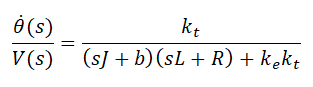
Since the two constants are the same (Kt = Ke), we can also write it as:
