ROBOTICS
1. Introduction
In this section, you can learn about robotic manipulators. From the basic knowledge of space representation, going through forward and inverse kinematics, dynamics, and trajectory following.
2. Spacial representation
Robotic manipulation inplies that something, usually a tool, will be moved around in space by some actuator. This naturally leads to the need of representing the location of the tool, as well as the other parts of the robot. There are a few possible types of coordinates systems that we can use to describe the position and orientation of a mechanism. The main one that we'll adopt here is a cartesian XYZ representation, but others, such as spherical or cylindrical are also possible.
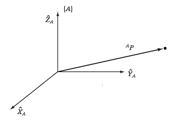
Once a coordinate system has been established, we can locate any point in it with a 3x1 position vector. Because we will often define many coordinates systems within a robot, we need a representation to indicate to which system they belong. We'll use a superscript attached to the vector name to represent this. For example, below we have the vector that describes the position of the point P in the coordinate system A:

Although this vector is enough to tell us the position of the point, it can't tell us its orientation. For instance, if P represents the point between the fingertips of a gripper, as illustrated below, we don't know which direction it's facing, or how it's rotated. In other words, the hand could be oriented arbitrarily while keeping the point between the fingertips in the same position in space. Therefore, to have a full description of that point, we also need to know it's orientation.

Imagine that we want to know only the direction of the arm above. What would we need? If we already know P, the only thing that we need is another point. The vector formed from P to this point gives us its direction. This new point, just like any other in that coordinate system, is made of 3 values, indicating its magnitude in each of the XYZ axis. In the image above this direction vector is given by . From that, the same logic applies for us to calculate the other two arm directions. Hence, the orientation of a body is given by 3 unit vectors that form a 3x3 matrix. Notice also that the orientation also forms what we call a frame, which is another coordinate system. So we can also say that in order to know the orientation of a body, we attach a coordinate system to it and then give a description of this coordinate system (in this case B) relative to the reference system (in this case A).
In the example above, we're describing the orientation of the arm, which is given by the coordinate system B, in terms of A. We denote the unit vectors giving the directions of the three main directions of B:
And when written in terms of A, we denote them:
It is convenient to stack these three unit vectors together, as columns of a 3x3 matrix, that we'll call a rotation matrix. Because this matrix gives the orientation of B relative to A, we'll write it as:

If we recall that the components of any vector are simply its projection onto each of the unit directions of its coordinates system, we can write the scalars in the rotation matrix as the dot product of the respective unit vectors:

Since the dot product of two vectors is given by their absolute values times the cossine of the angle between them:
And in this particular case their magnitude is one, the components of a rotation matrix are often called direction cossines.
In summary, what we'll do to describe how a body is located in space is attach a frame to it, whose origin will be described by a point (3x1 vector), and whose orientation will be described by 3 unit vectors (stacked together forming a 3x3 rotation matrix).