ROBOT ARM: PART IV
1. Introduction
Now that we are able to move the end-effector at a chosen velocity, we can develop one of the most interesting things about robot manipulators: path-planning and path-following algorithms. This opens up many possibilities for different applications, such as painting, obstacle avoidance, optimizing tasks by finding the best trajectory, among others. In this part, we'll develop path-planning and path-following models for the manipulator to follow a set of waypoints both when just moving and when picking up and dropping off an object.
2. Path-Planning Algorithm
We are going to perform this task using a Matlab livescript. It would be better to have a more interactive app with buttons, but unfortunately the App Designer in Matlab was crashing a lot when using the tools from the image processing toolbox, so we had to use a script instead.
The way it works is that the user first plots the waypoints that he wants on the XY plane by clicking on it. He then can click and drag the points to better position them. Next, the same set of points is shown in the YZ and XZ plane, where the user can again drag them to place them exactly where he wants. Finally, a smooth spline is generated passing through the chosen coordinates and is shown in 3D. The spline points are then sent to the workspace, from where the Simulink model uses it on the simulation. We've also created a function located at the end of the algorithm to check if all the points on the path are reachable. In this case, we want the last link to always maintain an angle of 0 degrees with the base plane, so the calculations are done based on this configuration. Any unreachable point is marked red on the final plot. Let's take a look at the script:
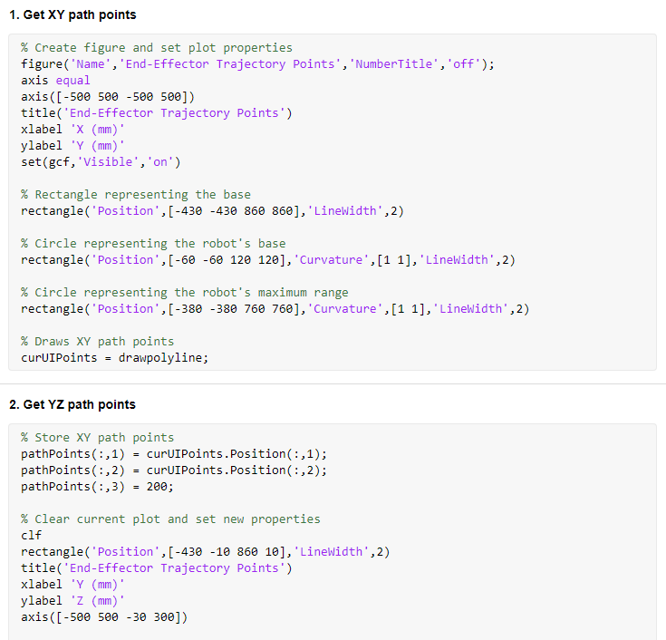


The checkCoords is the function that verifies if all the points are reachable. Let's see it too:


Notice that in the script we have to choose between picking up an object or not. This changes the first and last Z coordinate to be the same as the object that we are going to grab. Now let's test it and create a few paths with it.
First, we'll draw a circle on the Z plane:
In this example, we only set the coordinates on the XY plane. By default, the first coordinates on the Z plane are all 150, and the user can change it as he wants by dragging them, as we'll see. Here's the final 3D path:

Now we'll draw a star, also on the Z plane:
Notice that our idea here is to test the path planning algorithm. The fact that our star is not made of straight lines is what we want, otherwise we could just easily make it go through the 11 original coordinates to get one with straight sides. Here's the 3D view:

Now let's draw a more random trajectory and also change the Z component:
Sometimes it's not so easy to see all the points on a plane, and we may drag an unwanted point. However, as we go through all three planes, it becomes easy to see and organize them the way that we want. Here's the final path:

Lastly, since we're also going to develop a model to pick up and drop off an object while going through a given path, we're going to create it now:
And the final path is:

To finish, let's see what happens when we select points that are unreachable. These points are either outside of the robot's reach, require angles that violate joint ranges, or would result in a collision with the robot itself:
The red points indicate the parts of the path that are unreachable:

Next, we're going to create models to follow these paths that we've saw.
2. Path-Following Model
Below is the model that we're going to use to make the end-effector follow the desired path. The only new block is the one from Stateflow. The others are the same from previous chapters:
Path-Following Model
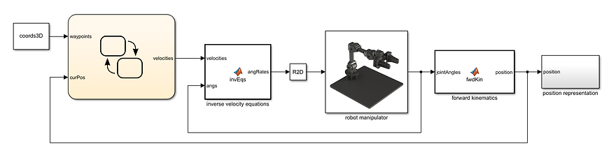
(click to enlarge)
Stateflow Chart

It's a simple feedback model. We go from one point to the other, and when we're within at least 1mm from it, we jump to the next.
Notice that we already have a model to move the end-effector at a chosen velocity in each of the XYZ directions. Now, however, to move from one point on the path to another, we're going to be working with a velocity vector on the 3D cartesian plane. This means that first we're going to need to decompose it in the XYZ directions so that we can use the inverse velocity (or inverse Jacobian) algorithm block:
Velocity Calculation Function

The function in our model does this. It uses the distance between the current and next point to calculate the projecting angles in each axis, and then with them, it calculates the required velocity in each direction so that we have the constant linear direction that we want (desVel). Below is a diagram showing basically what we're doing. The only difference is that in order for it to be easier to visualize we have the vector starting from the origin, instead of the current point in space:

Now let's test our model. A spline block from Simscape will be used to show the desired path on the simulation. It's being fed the same variable coords3D as our Stateflow chart. We'll use the paths that were generated on the previous section, starting with the circle:
As we can see the model works pretty well. Lets try the next path, the star:
Here we're moving the end effector with a velocity of 80 mm/s, and we can see that we get a smooth movement throughout the path, which is what we are aiming for. Finally, let's see the third path, which is a more random one:
It's clear that our model performs the way we intended. The algorithm could be further improved to include orientation as well and to make it automatically compute if there's another possible orientation for the positions that the tool is unable to reach at zero degrees, for example.
4. Moving objects
Next, we'll combine the previous model with the one from Part II to obtain a model that will pick an object located at the first path coordinate, move it along the desired trajectory, and drop it off at the last coordinate. The robot starts at an initial position and goes back to it after dropping the object:
Pick Object Model

(click to enlarge)
The Stateflow logic is also basically a combination of the two previous models. The robot goes from the starting position to one above the target, so that is no chance of hitting it. Then, it stops, moves down, stops again, and closes the gripper to grab the target. Once it's closed, it goes moves through the planned path until the last coordinate, where it drops off the object, moves above it so that it doesn't hit it, and then moves back to the original position:
Stateflow Chart


Pick Up Subchart

Drop Off Subchart

The velocity function is the same from the previous section, but we'll show it here again to keep the flow:
Velocity Calculation Function

Now it's time to see it working. First, let's use the last path that we generated on the previous section and see how it performs:
It performs very well, picking up and dropping off the object at the right locations, while following the path in between these points. Lastly, let's create another path and run another simulation to see it working again. Here's the path:

And the simulation:
This simulation also works well. We can conclude that our model is correct and our calculations accurate.
5. Conclusion
With this, we conclude the robot arm project. We went from the basic, regarding spatial representation, all the way to inverse velocities and path-following algorithms. The project could be further developed by constructing a real model and getting into the control part. We could also learn more about mechanical design and construct other grippers for the manipulator in order to perform different tasks.